A lighting-control decision becomes expensive when a building is almost finished. Drivers have arrived, ceiling zones have been wired, and the operator wants scenes that the installed controls cannot deliver. We start with the people using the space: who changes a scene, which luminaires need independent commands, how often the layout will change, and what the maintenance team will inherit.
A hotel room, an office floor and an RGBW façade rarely benefit from identical controls. The first two may share a DALI-2 backbone. The external lighting may need a separate DMX512 network. A warehouse with a few fixed dimming zones can be served well by 0–10V. The decisive factor is the operating brief, written before driver procurement.
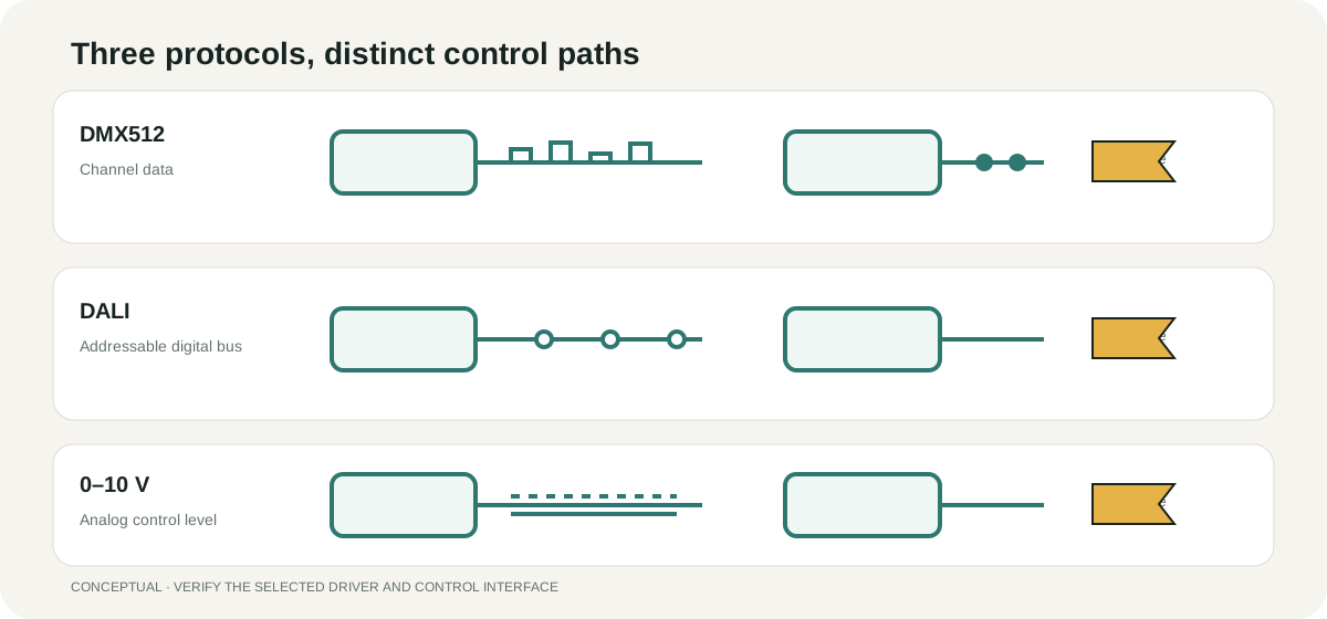
Protocols at a glance
| Comparison point | DMX512 | DALI / DALI-2 | 0–10V |
|---|---|---|---|
| Signal type | RS-485 serial data, 250 kbit/s | Two-wire digital bus, 1200 baud, polarity-independent | Analogue DC voltage |
| Link capacity | Up to 512 data slots per Universe; fixture count is calculated from each fixture’s channel use and is theoretical address capacity | Up to 64 control-gear addresses and a separate 64 control-device addresses per subnet; 16 control-gear groups, 32 control-device groups and 32 input-device-instance groups (each instance may join up to three groups); 16 scenes per gear | No device addresses; quantity depends on controller capacity and connected loads |
| Dimming resolution | 8 bit per channel (256 levels); some fixtures support 16 bit | Standard logarithmic curve; actual minimum output depends on the driver | Depends on the driver curve; some products have a minimum level around 1%–10% |
| Two-way feedback | No for basic DMX; supported devices may use RDM | Available where the relevant devices and controller support it | No native digital device feedback |
| Wiring topology | Daisy-chain with 120 Ω end termination; 32 Unit Loads is a traditional RS-485 design reference, not a fixed device count | Star, tree or bus; do not form a ring | One control pair; more zones usually mean more control wiring |
| Distance | Follow the applicable standard, cable and equipment documentation | With 1.5 mm² conductors, the recommended maximum spacing between the two furthest devices is 300 m; also check current, voltage drop and cable capacitance | Depends on voltage drop and driver behaviour; verify long runs |
| Colour control | Well suited to multichannel dynamic effects | Requires colour-control gear such as compatible DT8 equipment | Not part of the basic interface; additional compatible channels or controls are needed |
| Commissioning | Set start addresses and channel modes; program scenes | Discover and address devices; configure groups, scenes and sensors | Assign zones; set and verify minimum/maximum levels |
| Relative cost | Controller and decoder cost varies; programming may require a specialist | Drivers and bus power add cost; reconfiguration is flexible | Often a lower hardware cost for a small, simple system |
| Typical applications | Façades, wall washers, stages and landscape effects | Hotels, offices and commercial interiors | Office zones, warehouses and simple downlight circuits |
Hotels: pay for reconfiguration where it will be used
Guest rooms and meeting suites need repeatable, intelligible scenes. A hotel may reconfigure conference spaces, change furniture arrangements and add sensors after handover. DALI-2 earns its cost here: fixtures are addressed individually, then assembled into groups and scenes through commissioning software. A partition moves and the control group can move with it.
IEC 62386 defines the DALI protocol. Its polarity-independent two-wire bus communicates at 1200 baud, typically around 16 V. Each subnet permits up to 64 control-gear addresses and 64 separate control-device addresses. Control gear supports 16 groups and 16 scenes per gear; DALI-2 control-device and input-instance groups have their own address rules. Those numbers set the boundaries for the control schedule before the first ceiling circuit is installed.
The separate grouping limits matter when planning sensors: there are 32 control-device groups and 32 input-instance groups, and an input instance may join up to three of the latter. Some products contain several logical units and consume several addresses. These distinctions are set out in the DALI Alliance Quick Start Guide; they should not be collapsed into a single “64 lights” claim.
Bus power has its own budget. Total bus-power output is limited to 250 mA. DALI Alliance guidance describes a maximum 300 m separation between the two furthest devices with 1.5 mm² conductors at the full 250 mA bus-supply rating; Tridonic uses a 2 V maximum drop in its wiring guidance. Star, tree and bus routing are available; a closed ring is excluded. Do not assume that a roughly 16V DALI bus is SELV: insulation, segregation and installation must follow the selected equipment instructions and local rules. The bus supply serves communications and compatible bus-powered devices; the LED driver supplies the light source. Tridonic’s DALI manual explains the cable and voltage-drop calculation.
An adjacent corridor run also reveals colour differences rapidly. For visible, repeated fittings, we would request a documented colour-consistency tolerance such as 3 SDCM or less because the eye compares one luminaire with the next as guests walk along the corridor. That requirement belongs on the luminaire order beside CCT and Ra, separate from the choice of digital control.
That is an example procurement target, not a verified FANXING colour-bin rating or a universal hotel standard. ERCO explains SDCM and colour consistency; require the selected luminaire’s declared tolerance and a side-by-side sample review before ordering.
Colour-changing DALI equipment needs the relevant functions. IEC 62386-209 / DT8 covers Tc, RGBWAF and xy colour types. D4i adds luminaire-oriented features including data and integrated bus-supply options. The exact driver entry in the DALI Alliance database establishes DALI-2 certification status; a general claim of “DALI compatible” provides less information to a buyer.
Keep an obvious local manual override even where automation is extensive, for the guest experience as much as for the staff. The staff should understand a room scene from the wall panel without a programming laptop. That is a procurement decision as much as a software decision.
For a hotel scheme, put the driver's complete part number and the saved scene configuration in the handover file. Years later, room staff should be able to change a scene without reconstructing the electrical design.
The procurement route follows the application: hotel lighting and commercial downlights need a driver schedule; outdoor wall washers need both an optical and a control plan. Our wall-washing and grazing guide addresses the first of those decisions.
Façades: synchronisation earns DMX512 its place
Dynamic RGBW lighting needs continuous channel values, predictable fades and a consistent controller patch. DMX512-A under ANSI E1.11 transmits at 250 kbit/s; a full 512-slot packet refreshes at about 44 Hz. One 8-bit channel gives 256 levels. Sixteen-bit dimming uses additional channel slots for finer transitions, especially noticeable in slow low-level fades across an even wall.
A standard four-channel RGBW personality has a theoretical address capacity of 128 fixtures per Universe; an eight-channel mode reduces that calculation to 64. For detailed address planning, see the FANXING DMX512 wall-washer installation article. An optically isolated splitter builds independent physical branches while preserving the existing Universe channel map.
For comparison, a three-channel RGB mode yields floor(512 ÷ 3) = 170 theoretical address blocks. Eight-bit values run from 0 to 255; sixteen-bit pairs provide 65,536 code combinations where the fixture implements them. Neither code count guarantees a particular dimming curve or smoothness. The fixture personality remains authoritative, and a splitter adds physical branches, not another Universe. ENTTEC’s DMX overview distinguishes channel data from physical distribution.
The network begins with 120 Ω shielded twisted-pair cable, a daisy chain and a 120 Ω terminator at its actual endpoint. Traditional RS-485 planning uses 32 Unit Loads per segment; modern receivers may impose fractional loads. Cat5e is also used where the system provides its conductor pair, connector pinout and termination arrangement. Long elevations are easier to commission with a splitter output for each logical route.
Basic DMX data travels in one direction. RDM, described by ANSI E1.20, adds discovery and supported remote management functions. For sites requiring many Universes, sACN under ANSI E1.31 transports DMX-style data over IP networks; Art-Net is another common network transport. Receivers or gateways at the building edge convert that transport into the controller data required by the luminaires.
When a DMX branch runs smoothly near the controller and erratically towards its end, the first diagnosis is the physical data path: termination, passive branches, connectors and receiver loading. Testing that path segment by segment is more productive than changing the programmed scene.
Offices and fixed zones: keep 0–10V straightforward
Many office fit-outs need occupancy control, daylight response and a few dimming zones. DALI-2 works particularly well when tenants may redraw partitions and managers want addressing or status functions. A stable plan with fewer, larger zones can use a 0–10V analogue pair with simpler hardware and minimal software maintenance.
The controller and driver must agree on their electrical interface. Different standards and regional practices use different control-current arrangements. The procurement schedule should state, in writing, whether the driver sources or sinks control current, its rated current, the corresponding controller capacity and the intended wiring polarity. A dimming response can be linear or logarithmic. Some products bottom out around 1%–10% light output; a low-end command may leave the lamps visibly on. Specify a supported dim-to-off function or a separate switching device when the room needs full darkness.
We check the combined control current before counting drivers. With an illustrative 50mA sink-rated controller and drivers each sourcing 0.5mA, 50 ÷ 0.5 = 100 is a current-budget result only. Relay rating, inrush, wiring loss, tolerances and the manufacturers’ permitted load count can impose lower limits. Those figures are hypothetical interface values, not FANXING product specifications. Analogue 0–10V and PWM are different interfaces; a “dimmable” label does not establish compatibility.
One control pair normally moves its connected drivers together. More independent zones require more control circuits. DALI and 0–10V cannot be directly interconnected: an active interface must translate commands, electrical behaviour and any required feedback.
Distinguish a driver fault from a control fault
| Symptom | Possible cause | What to check |
|---|---|---|
| DMX fixtures flicker or change colour randomly | Missing termination, unsuitable cable or poor connection | Check the end terminator, replace the cable or shorten the segment |
| Fixtures at the end of a DMX line behave incorrectly | The designed Unit Load or signal-quality limit is exceeded | Check receiver Unit Loads and add a suitable splitter or repeater |
| DMX fixtures respond at the wrong positions | Start address or channel mode does not match | Compare the fixture manual with the controller patch |
| DALI devices cannot be found | Bus supply is inadequate, shorted or not powered | Measure bus voltage/current and isolate the line by sections |
| DALI address conflict | A replacement or previous device retains a duplicate address | Commission and address the devices again |
| 0–10V will not dim to the expected minimum | Driver minimum-output limit | Check the driver data sheet; replace the driver if required |
| 0–10V flickers at low output | Incompatible driver/control or control-wire voltage drop | Verify source/sink direction and curve; shorten or recalculate the run |
| 0–10V fixtures do not turn off | Minimum dim level is not the same as off | Add a relay or use a driver with documented dim-to-off support |
Mixed-use buildings: decide who owns the gateways
A mixed-use development can run DALI-2 for hotel rooms and office areas, DMX512 for exterior colour and 0–10V for a small service zone. This split is preferable to forcing every area onto one protocol because it matches the commissioning effort to the work each space performs. The building management system should receive an agreed scene schedule, status requirements and loss-of-communication behaviour before gateways are selected.
Emergency and life-safety lighting adds another layer of coordination in occupied buildings. Its operating state is established by the building's required safety design, while decorative control scenes remain subordinate to that function. A fault in the entertainment or façade controller should not cause a corridor to lose the normal lighting state anticipated by the facility manager.
A gateway purchase should name both supported interfaces, the mapped commands, restart behaviour and the company responsible for commissioning. This avoids the familiar disagreement in which the lighting contractor considers the dimmers complete while the automation contractor expects scene integration to have been included.
Put the interfaces into the purchase schedule
| Control method | Equipment to identify | Documents to request |
|---|---|---|
| DMX512 / RGBW | DMX512-A-compatible controller; signal splitter if required; built-in DMX receiver or external decoder; matched LED power supply or driver | Controller and decoder models; channel chart; start-address plan; signal and power diagrams; termination requirement |
| DALI / DALI-2 | Compatible DALI controller, bus power supply and LED control gear; colour-control equipment only when the required function calls for it | Model and certification status; bus-supply capacity; address/group list; driver functions and wiring instructions |
| 0–10V | 0–10V control unit; dimmable driver with matching source/sink behaviour; switch or relay if required | Control and driver interface specifications; control current; load count; dimming curve; minimum level and dim-to-off behaviour |
For DALI, discover and address devices, configure groups and scenes, then save the controller configuration and verify bus-failure and power-recovery states. For 0–10V, test the actual driver/control pair at minimum, maximum and full-off commands. For DMX, match fixture modes and addresses before judging fades. These acceptance tests belong to the named commissioning scope.
Technical reading: ESTA published ANSI E1.11 and ANSI E1.20 standards; DALI Alliance systems and addressing guidance; DALI Alliance Quick Start Guide; ANSI C137.1-2022 listing; Lutron control-topology note.
A 48V supply voltage does not itself establish a control protocol; the 48V magnetic-track guide separates those functions. FANXING’s custom-lighting service and manufacturing process provide context for matching the fixture, driver and project documentation; exact model support is confirmed in the quotation.
For a control proposal, send the fixture schedule and the scenes the operator needs. FANXING can align driver options, address groups and control interfaces with the lighting package through the project inquiry page.