The first wall washers change colour correctly. Halfway along the façade, the scene still looks stable. At the far end, the last fittings flicker, show an unexpected colour or restart when the controller calls for full white. These symptoms can appear similar from street level, yet they lead to different parts of the installation.
Before changing programme settings, we separate four fault patterns. A controller patch controls behaviour; the data network carries that behaviour to each receiver; the power system supplies the luminaire. A problem in one layer calls for a different test in the others.
| Symptom | First place to investigate | Fast isolation test |
|---|---|---|
| Entire branch unresponsive | Controller or splitter output, first connector, data polarity, branch power | Connect one known receiver using a short confirmed data lead |
| Fittings respond but colours are wrong | RGBW channel order, fixture personality, controller patch | Command red, green, blue and white separately at one luminaire |
| Last fittings flicker or change unexpectedly | Passive branch, cable or connector, receiver loading, termination | Divide the line into shorter sections and terminate the current endpoint |
| Fittings reset when full white is selected | Supply capacity, voltage drop, power connector or driver | Check the supply and far-end voltage with the high-load scene active |
Four symptoms also imply four different owners on site. The controller programmer resolves a wrong personality; the data installer repairs a cable or splitter branch; the electrical contractor diagnoses power drops; the luminaire technician can test the receiver itself. Naming the fault category early reduces repeated visits where each trade tests only its own equipment. The handover documents should preserve that separation.
When a stable first section turns erratic after another group is connected, work back from the last responsive fitting; the fault usually sits at one data joint or an uncontrolled branch. Full-white restarts point elsewhere: the data can be fine while the electrical feed sags.
One data route, one power route
DMX512 is a serial control protocol under ANSI E1.11. The controller transmits data to receivers integrated in wall washers or housed in separate decoders. The reliable route is controller → optically isolated splitter where branches are needed → first receiver → subsequent receivers → final receiver and end terminator.
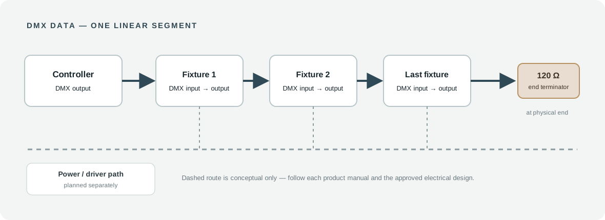
An optically isolated splitter provides a driven output for each branch, improving isolation and making a failure easier to locate. A passive Y split creates two uncontrolled data paths and can produce reflections. Traditional RS-485 design uses 32 Unit Loads per segment; the actual number of receivers is established from the loading of the installed equipment. A splitter distributes a Universe physically while keeping its channel allocation unchanged. The comparative control architecture is covered in FANXING's protocol article.
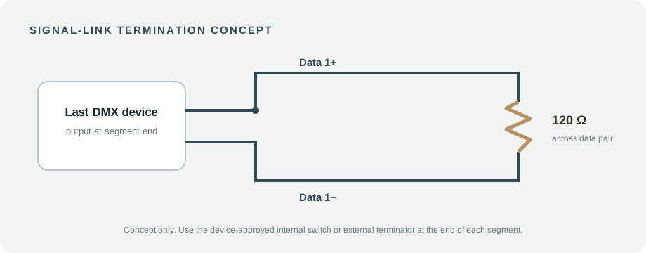
The primary data run uses 120 Ω shielded twisted-pair cable with a 120 Ω resistor at the end of the last receiver. Cat5e can carry a DMX data pair when the connector mapping, cable pairs and termination have been designed as a system. Size each branch to the published limits of its controller, splitter, receivers and cable. ENTTEC’s planning guidance discusses runs up to about 300m with suitable cable and termination; that is manufacturer guidance, not a universal E1.11 guarantee or a substitute for the selected equipment’s limit. A route with heavy interference, poor connectors or high receiver loading may need shorter sections.
Power has its own cable route. A built-in receiver may be part of an AC-input luminaire or a DC-input assembly; an external decoder may drive a separate constant-voltage RGBW load. Both arrangements demand a power diagram showing supply location, branch protection, fixture voltage and accessible connectors. The data route should have its own drawing, with controller ports, splitter outputs, receiver order and terminators clearly labelled.
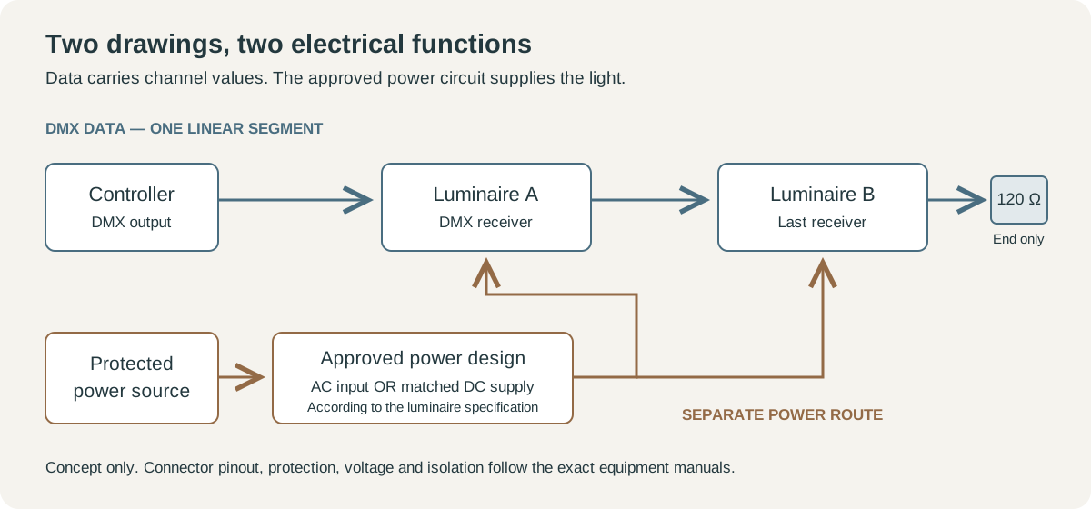
For the DC case, a hypothetical 24 V, 120 W load draws 120 ÷ 24 = 5 A before wiring losses. This is a calculation example, not a FANXING specification. Check the driver/decoder output type: a constant-voltage PWM decoder is not interchangeable with every constant-current fixture. Supply margin follows the actual derating and start-up requirements; a fixed percentage is not a universal rule. Mains work, isolation, protection and outdoor connections require qualified installers working to the approved design. Isolate power before modifying a connection.
For a long architectural elevation, use one logical splitter output per façade section because maintenance teams can isolate the affected branch without losing the entire display. Where a façade turns a corner, the splitter cabinet often offers a better dividing point than an arbitrary count of fittings. Branches can follow the physical building elevations and carry matching labels on the output ports, cables and luminaire schedule. A service technician can then reproduce the topology from a drawing without tracing the entire site cable route from the control room.
Pin connections and the adapter problem
The standard primary DMX512-A data assignment is shown below. Architectural products may instead arrive with 3-pin XLR connectors, sealed waterproof plugs, loose tails or terminal blocks. A 3-pin-to-5-pin adaptor must preserve the primary differential pair and the common reference.
| Pin | Signal |
|---|---|
| 1 | Data-link common (signal reference) |
| 2 | Data 1− |
| 3 | Data 1+ |
| 4 | Data 2− (reserved in a single-link installation) |
| 5 | Data 2+ (reserved in a single-link installation) |
The common three-pin convention uses pin 1 for common, pin 2 for Data 1− and pin 3 for Data 1+. Pins 4 and 5 on a five-pin connector are allocated to the optional second data link. Changing connector shells does not add another Universe. A connection schedule should show the view from which the pin numbers are read. Looking into a plug and looking into a socket can reverse the apparent left-to-right order. Drawing both mating faces makes the assembly easier for the installer to check. The signal pair and cable shield also need a consistent termination method across accessories and distribution boxes, especially where the control cabinet and outdoor installation use different connector styles.
Cable colour alone is an unreliable identity for Data 1+ and Data 1−. Trace the pair through adapters, junctions and extension cables. A single reversed connection can create a dark branch; an intermittent joint at the end can look like a programming fault when viewed from the ground.
Addressing a four-channel RGBW wall washer
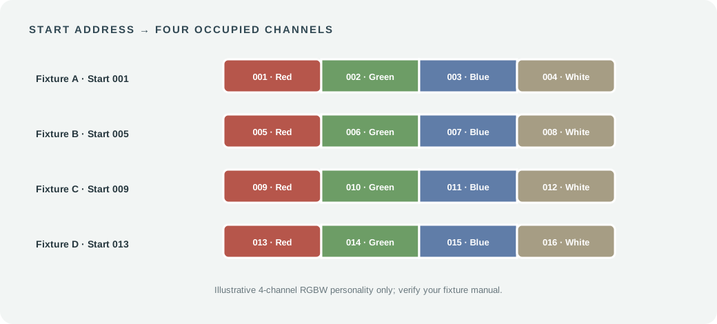
A basic RGBW fixture may use four consecutive slots: red, green, blue and white. In that mode, four independently controlled units can use starting addresses 001, 005, 009 and 013, occupying 001–004, 005–008, 009–012 and 013–016. A controller personality with a master-dimmer or strobe channel will have a different patch. The fixture mode and controller map must match.
Record the occupied slots as well as the start
| Fixture | Starting address | Occupied slots |
|---|---|---|
| RGBW wall washer A | 001 | 001–004 |
| RGBW wall washer B | 005 | 005–008 |
| RGBW wall washer C | 009 | 009–012 |
| RGBW wall washer D | 013 | 013–016 |
A Universe carries 512 control slots (channels), not 512 physical receivers. Four-channel RGBW gives 512 ÷ 4 = 128 theoretical address blocks; an eight-channel mode gives 64, and a three-channel RGB mode fits floor(512 ÷ 3) = 170. The traditional 32 unit loads per physical segment, cable, splitter and power budgets remain separate. Each 8-bit value runs from 0–255. The actual fixture channel chart determines whether master dimming, strobe, pixel channels or 16-bit pairs change the allocation.
Older receiver designs make addressing visible through DIP switches. In a nine-switch address bank with binary weights 1, 2, 4, 8, 16, 32, 64, 128 and 256, start address 37 = 32 + 4 + 1. Switches 1, 3 and 6 are ON, and the other address switches are OFF. Manufacturers can number and arrange their switches differently; the actual switch legend determines which position carries each weight.
Digital-display receivers usually allow the starting address and personality to be set by menu keys. RDM-compatible equipment under ANSI E1.20 can support discovery and remote addressing when the controller and receiver support RDM and any splitter or repeater that must carry the management traffic is correspondingly compatible. That facility is especially useful when fixtures are difficult to access after installation.
If several fittings should copy the same scene, they may share the same starting address and mode. For independent effects, assign their address blocks separately and record the results in the controller patch. The detailed Universe arithmetic belongs in the broader control comparison; commissioning here focuses on the real receiver sequence and the electrical link.
Commissioning a façade, step by step
A reliable start uses one known receiver, a short data lead and the correct supply. Test red, green, blue, white, fade and blackout. Then attach the next fixture in physical order, preserving the terminator at the actual end of the temporary chain. When a complete segment is stable, move to the next splitter output and repeat. This routine establishes one known-good reference before the full elevation is energised.
One column in the address schedule should name the intended group or effect. The physical address tells the controller where to send levels; the group name explains what the operator expects to see. When a façade is divided into entrance, side elevation and feature zones, those names make controller handover and future scene editing far faster. The address can remain constant even when the artistic grouping changes.
The as-built schedule should map each luminaire position to its Universe, splitter port, starting address, fixture mode, supply zone and junction-box location. The controller file and the two wiring drawings belong with that schedule. A replacement fitting can then be set up from records instead of guesswork.
The equipment record should retain the exact controller/gateway, receiver/decoder, supply and splitter model numbers, data-pin assignment, receiver loading, input voltage and current, channel chart and environmental instructions. For a documented project supply, custom-lighting coordination and the manufacturing process explain the scope to agree before ordering.
Data termination will not restore lost power: when a supply handles a modest colour scene but drops out as all RGBW channels rise, test the electrical feed under the full-load scene, covering output capacity, cable voltage drop and connections. A wrong shade on every otherwise responsive fitting points back to the channel personality and patch instead.
A power-recovery exercise finishes the commissioning. Restore supply after a normal shutdown and observe the returning scene. Receiver memory, external decoders and gateways may restore different states; the control schedule should express the intended night-time result so the same behaviour can be checked at handover.
Keep every junction and the final terminator reachable without dismantling decorative cladding: a technician should be able to disconnect one junction, attach a short reference lead and retest. Place data and power joins where they can be inspected, route cables with drainage in mind, and show junction-box positions on the architectural elevation as well as the electrical plan, because one failed connection behind an inaccessible panel turns a small repair into an expensive one.
For a new RGBW façade, the optical decision deserves attention before the controller patch is locked. FANXING's wall-washing and wall-grazing article covers the choice between even illumination and texture-revealing light.
Technical references: ESTA's published ANSI E1.11 and E1.20 standards; ENTTEC’s DMX overview and termination guidance.
For the optical and purchasing route, compare outdoor wall washers within the wider outdoor-lighting solutions. A fixture’s power input and control interface must be confirmed before a controller or decoder is selected.
Send the elevation, quantity schedule, preferred fixture mode and existing controller information through FANXING's inquiry page. The data map and electrical supply drawing can then be prepared as a matched set.