The ceiling drawing shows a single line through a retail corridor. The electrical drawing needs to show the load behind that line. In this design exercise, twenty-four 10W spotlights and four 20W linear modules create a connected load of 320W. Their positions may change when the store changes its displays; the power system must remain orderly when that happens.
A 48V magnetic track carries power from a DC supply through a feed and conductive rails into compatible luminaire adaptors. Magnets support positioning and retention; the contacts deliver the current. Track, connectors, adaptors, luminaires and supply belong in one matched system. A module can sit inside a rail profile and still have the wrong contact position or electrical arrangement.
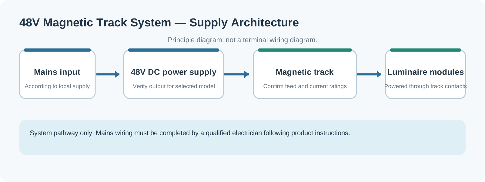
The 320W calculation determines the first drawing
We begin with P = V × I. At 48V, 320W ÷ 48V = 6.67A. Using an 80% preliminary loading target gives 320W ÷ 0.8 = 400W of combined nominal supply capacity. That figure sets a useful margin for component selection; conductor rating and voltage drop still determine how power is distributed along the track.
Two electrically separate 160W sections, each provisionally paired with a dedicated 200W-class supply, are one candidate layout for this design exercise, subject to the documented ratings of every component. Each 160W section draws approximately 3.33A at 48V. Splitting the feed reduces the distance travelled by the highest current, provides independent fault isolation and keeps the power units accessible above the ceiling. The two supplies serve separate rail sections; their outputs are not joined on one continuous conductor.
FANXING's MG26 accessories include MG-P100W (100W) and MG-P200W (200W) supplies. The available catalogue gives MG-TQ26-CB’s profile dimensions but does not establish its continuous current rating. Obtain the written rail, feed and connector ratings before approving either 3.33A section; the calculated 6.67A total is a demand figure, not a verified track capacity. Even when the corridor is divided, the feed terminals and each section need their own current allocation.
The module power basis must also be consistent: confirm whether watts describe track-side input or LED-source power. Allow for start-up behaviour, ventilation and the supply’s temperature-derating curve. A constant-voltage 48V supply must not be replaced with an arbitrary constant-current driver. The catalogue MG-P200W is a capacity reference; its name and wattage alone do not prove compatibility with every series in the table below.
Why choose 48V? At equal power, higher voltage means lower current. For 240W, 24V demands 10A while 48V demands 5A. On identical conductor resistance, the 48V option halves the absolute voltage drop; the relative voltage loss and I²R heating fall to about one quarter.
| Comparison | 48V magnetic track | 24V low-voltage track | 220V conventional three-circuit track |
|---|---|---|---|
| Supply | 48V DC | 24V DC | Mains AC |
| Current at equal power | 1× | About 2× | About 0.22× by ideal voltage ratio only; AC power factor also matters |
| Voltage drop over a long run | Low in comparison | Moderate; long runs may need sections | Relatively lower, but still depends on length, power factor and conductor parameters |
| Track appearance | Narrow profile, suited to a minimal ceiling | Narrow profile | Wider |
| Driver location | In the module or system DC/DC stage | Similar | AC driver in the luminaire |
| Interface interchangeability | Often manufacturer-specific | Often manufacturer-specific | More standardised |
| Installation | Mains connection by a qualified electrician; install the track side according to the system safety classification and instructions | Similar | Mains throughout; stricter installation requirements |
| Typical applications | Hotels, retail, offices and high-end homes | Small spaces and short runs | Larger spaces, higher power and applications needing broadly standardised luminaires |
Where the last light receives its power
A voltage-drop calculation makes the power drawing more useful than the decorative reflected-ceiling plan. Take a 10m run with an outgoing-and-return loop resistance of 0.02Ω/m, an assumed value for this worked example rather than a measured MG26 rail specification. Total loop resistance is 0.2Ω. For approximately uniform distributed current and one-end feeding, the simplified far-end drop is total current × loop resistance ÷ 2. It neglects contact losses and the change in constant-power module current as voltage falls, so it is an initial estimate, not a product test.
For a 48V, 240W load, current is 5A and the estimated drop is 5 × 0.2 ÷ 2 = 0.5V, about 1.0%. At 24V, the same 240W draws 10A, giving 1.0V, about 4.2%. Track joints and connectors add resistance at real installation points. Feed placement deserves as much attention as the nominal rail length.
A centre feed divides the current paths towards both ends. Two separate zones achieve a similar practical benefit where the ceiling layout allows it. Set the permitted voltage-drop budget from the supply tolerance and the module’s documented input-voltage window. A single percentage cannot replace those limits. Record the most distant module voltage with the full load active and compare it with that window.
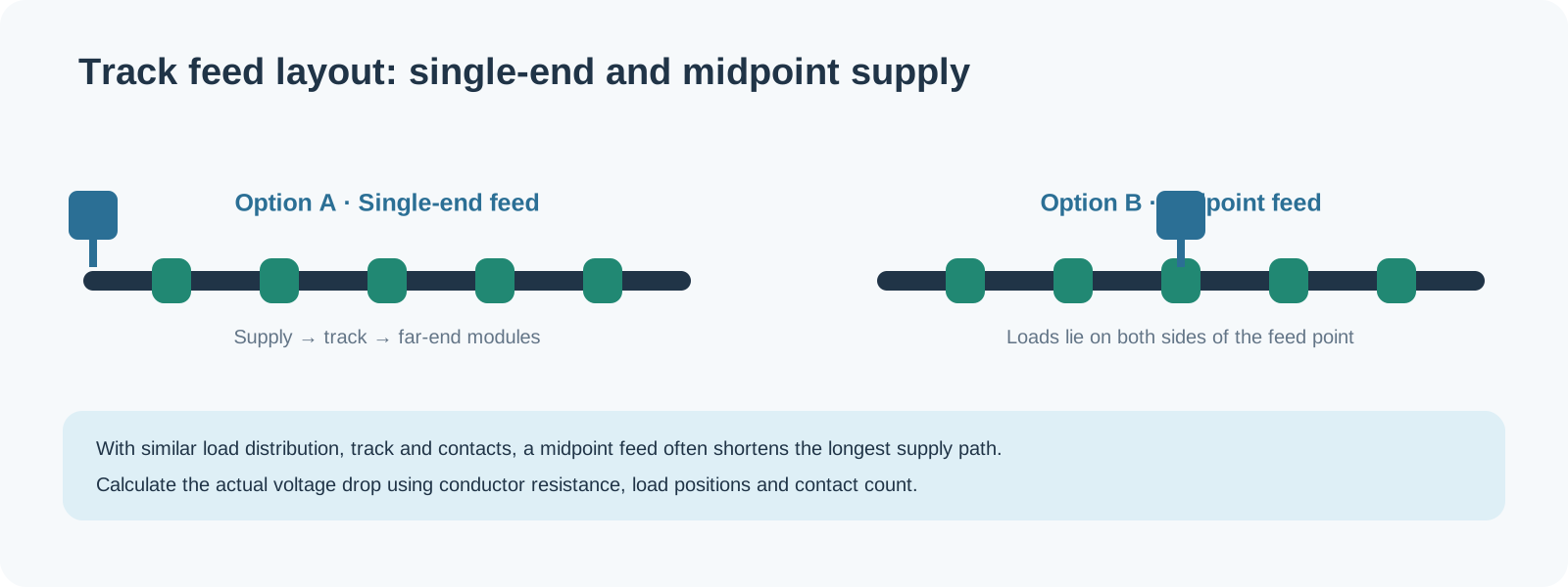
The MG26 module example helps check the supply choice: eight MG-F12W units at 12W plus ten MG-F6W units at 6W total 156W. Dividing by 0.8 gives 195W of nominal supply capacity, which makes the catalogue MG-P200W a 200W candidate for technical review, not an approved combination before its output, rail, feed and module interfaces have been confirmed. The supply, feed and rail are scheduled together because one missing feed adaptor can hold up a complete ceiling installation.
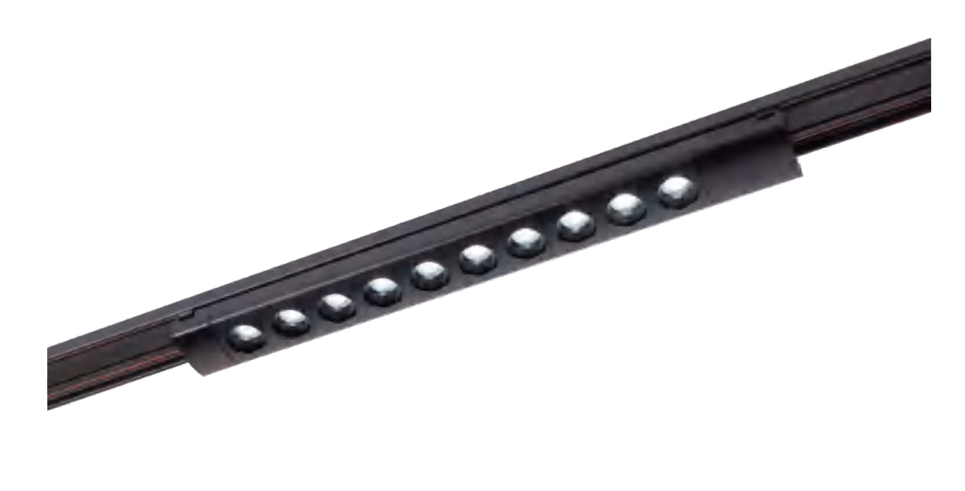
The catalogue family matters more than the photograph
| 48V family | Catalogue model examples | Catalogue power | Product form and notes |
|---|---|---|---|
| L20 magnetic system | L20/FGD-300, L20/FGD-600, L20/FGD-1200 | 12W, 18W, 36W | Floodlight linear modules; catalogue lists 120° and black/white finishes |
| M35 magnetic system | M35/GS-10, M35/GS-20, M35/GS-30 | 10W, 20W, 30W | Grille modules; catalogue lists 24° and black/white finishes. M35/GD spotlights are also listed |
| MG26 ultra-thin magnetic system | MG-F6W, MG-F12W | 6W, 12W | Floodlight modules; catalogue lists Ra > 90. Select the matching MG26 ultra-thin track and accessories |
| L8 48V magnetic system | L8-F8W, L8-G4W, L8-G8W | 8W, 4W, 8W | Floodlight/grille modules; catalogue lists Ra > 90 |
The MG26 accessory range includes MG-TQ26-CB, an ultra-thin track approximately 26 × 6mm, and the MG-P100W and MG-P200W power components. Record the rail series, adaptor, feed connector and supply on the same purchase schedule. The luminaire dimensions alone cannot confirm that two series use the same electrical contacts.
Recessed mounting suits new ceilings with planned voids and access panels. Trimless recessed track gives a clean plaster edge but commits the builder to tighter finishing tolerances. Surface-mounted rail is easier to maintain in a refurbishment. Suspended rail gives flexibility in high lobbies and retail spaces, with suspension points and wiring coordinated into the ceiling design. A trimless profile needs decisions earlier than a surface-mounted one: plasterboard thickness, the plaster edge, straightness through corners, and how the system will be serviced after painting. Suspended systems need their own visual coordination, because poorly aligned suspension points can undermine a minimalist line of light. Track length and finish should be approved against the reflected-ceiling drawing before cut sections are dispatched.
The key construction question is where the supply and joints can be reached after handover.
A 48V label does not by itself establish SELV, separation, fault protection or a certification pathway. We ask for the documented mechanical interface, contact count and spacing, polarity, current ratings, module input range, supply specification and dimming arrangement as one system. Review a representative sample before closing the ceiling, and retain the approved BOM and wiring instructions for replacements.
Optics still decide whether the corridor feels comfortable
The corridor example uses a low-power spotlight and a linear component, yet wattage alone will not deliver a calm ceiling. For a warm hotel corridor, we would compare 2700K and 3000K samples, request Ra ≥ 90 where colour quality is a project priority, and compare available 24° or 36° accent optics at the actual mounting height. Those are example design choices, not a hotel standard or a promise that every series offers every combination. The catalogue lists 24°/36° options for named L20 grille and M35/GD models; the M35/GS models in the table are listed at 24°. For repeated fittings, a requested tolerance such as ≤ 3 SDCM needs a declared product value and side-by-side sample approval; it is not an independently verified FANXING binning specification.
For retail merchandise, compare narrower accents with the object size and viewing distance rather than prescribing one beam-angle range for every display. Compare 3000K and 4000K against the goods, and request Ra ≥ 90 and relevant R9 data where the merchandise warrants it. Office meeting-room references commonly use Ra ≥ 80 and a UGR limit of 19; a brief may request higher colour rendering. UGR must be assessed for the room, layout and viewing positions, not promised from a luminaire label alone. Comparing 3500K and 4000K is a design choice. For high-end residential rooms, the same 2700K/3000K and available 24°/36° comparisons can be sample-reviewed without treating them as mandatory values. Use the exact IES or LDT distribution for a calculation; availability must be confirmed for the selected model.
ERCO’s Skim documentation demonstrates warm-white and neutral-white options in a named manufacturer family; it does not specify FANXING stock. ERCO explains SDCM, and Zumtobel’s Lighting Handbook tabulates workplace colour-rendering and glare criteria. Confirm the currently applicable design brief and the exact product data before selecting modules.
Dimming also belongs on the same drawing. Supply-side dimming sends one controlled level along a compatible track section; module-integrated control allows individual or grouped adjustment. A DALI bus supply carries control communication, while the 48V supply carries luminaire power. For controller choices, see FANXING's lighting-protocol article.
A 0–10V input, DALI interface or wireless receiver must be confirmed on the actual supply or module; none follows automatically from a 48V rating. Do not join control-bus wiring to track power conductors.
What the control interface changes
| Architecture | How it works | Result | Typical use | Check |
|---|---|---|---|---|
| Supply-side dimming | A dimmable 48V supply or controller that is compatible with the system and explicitly supports the chosen interface | The track dims together | Corridors and a uniform ambience | Whole-track dimming and the protocol depend on the specific device specifications |
| Control in the module | The module includes a receiver, wireless or digital bus interface | Individual or grouped control | Retail, displays and changing scenes | More cost and commissioning effort |
On a finished ceiling, intermittent modules suggest contact or feed faults. A complete dark section sends the technician towards power and polarity. Flicker that changes with dimming levels points first to the control interface; uneven brightness at the end of the run calls for a loaded voltage measurement. A physically incompatible adaptor should be caught during the sample review, before dozens of modules reach site.
Follow the symptom through the system
| Symptom | Possible cause | What to check |
|---|---|---|
| Light does not turn on | No input, supply protection, reversed polarity or open contacts | Isolate power as required; check supply status and that the module is seated |
| Intermittent operation | Module not fully locked, dirty contacts or a loose connector | Refit the module and clean contacts according to the instructions |
| Flicker | Incompatible dimming, supply overload or loose contacts | Test at full output first; check supply and control separately |
| Uneven brightness | Far-end drop or different module configurations | Measure the far end under load and review feed locations |
| Dimming does not work | Control mismatch or missing bus supply | Check the control drawing and equipment schedule |
| Supply overload | Load exceeds rating or high-temperature derating | Recalculate; use a larger supply or divide the zones |
| Module will not fit | Different profile or adapter | Do not force it; confirm the exact series and model |
| Excessive temperature rise | Poor ventilation or overload | Disconnect power and have a qualified person check clearances and ratings |
Standards and commercial decisions
For China, general luminaire safety is assessed against GB/T 7000.1-2023 and LED controlgear requirements against GB/T 19510.213-2023, with GB/T 17743, GB 17625.1 and GB/T 18595 covering related EMC and harmonics topics. The national standards platform holds the records for 7000.1-2023 and 19510.213-2023.
For European orders, assess EMC, RoHS, the Low Voltage Directive where applicable, and relevant ecodesign requirements against the exact supplied configuration. A 48V DC module and a mains-input supply do not automatically have the same directive scope. If the buyer requires ENEC or another certification, obtain the genuine model-specific certificate; this article makes no FANXING certification claim. In Great Britain, CE and UKCA are both accepted for many regulated product categories under current guidance, while Northern Ireland has separate arrangements (UK Government guidance).
For the United States, the relevant published scopes are UL 1574 for track lighting systems and UL 2108 for low-voltage lighting systems, together with FCC provisions for the electronics (UL 1574 scope). Class 2 is a documented output/circuit classification, not something established by a 48V label or a power unit’s aggregate wattage. A commonly cited 100VA limit cannot be used alone to classify a 200W multi-output supply or an entire track system. Confirm the exact output ratings, listed system, isolation and permitted zoning with the responsible compliance specialist during quotation. No UL, ETL, CE or UKCA certification is claimed for FANXING by quoting these standards.
Related references: IEC 60598-1:2024, IEC 61347-2-13:2024, IEC 60570 and DALI Alliance systems guidance.
IEC 60570’s scope must be read before applying it to a low-voltage magnetic track; do not transfer an ordinary mains-track standard to every 48V configuration by analogy. The national standards cited above describe applicable technical subjects, not evidence that a particular product has passed testing.
FANXING offers samples. Most regular models have an MOQ starting at one piece, standard batch production usually takes approximately 25–30 days, and the warranty is five years under the order terms. With a complete project brief, preliminary zoning, feed and bill-of-materials guidance is usually provided in 3–5 working days. Special configurations are priced and scheduled with their own sample and production requirements.
The commercial-lighting range and manufacturing process provide context for the supply scope. Drawings, model-specific documents and order terms establish the final arrangement; a catalogue photograph does not establish rail current, control compatibility or certification.
Send the corridor drawing, rail lengths, fitting quantities and mounting preference through the inquiry form. The next document can be a matched track, module, supply and accessory schedule; product families and custom options are shown in FANXING's catalogues and custom-lighting service.
For an existing order or a document request, contact the FANXING team with the series and model number.